Struggles of Skoda Kodiaq Canton replacement
TL;DR: I don’t have a suitable solution. This is not a guide; it is a stream of thoughts to document how I got here.
If you are looking for a feasible Canton replacement, you probably need to find a solution to get the signal out of the factory amplifier to a digital signal processor (DSP) and then to an amplifier. I’ve also heard anecdotes about re-coding the car audio head unit to behave as a non-Canton one, which may be an option if you are in Europe.
And considering how much more effort it may still take, I’ve accepted the above fate, even though it leads towards a complex system with likely compromised quality (and also an overall expensive system as a bonus). Will be looking into getting high-level outputs from the factory amplifier to Helix DSP.
But I was trying to find a special way.
Input parameters
Skoda Kodiaq 2021 with Canton audio installed:
- 4 mid-bass,
- 4 tweeters,
- 1 centre speaker,
- 1 subwoofer, and
- 1 amplifier with DSP that drives everything above.
Sounds good for what it is, but doesn’t bring me joy.
Blindly replacing speaker drivers without replacing the amplifier is risky business, or at least without getting control over the sound levels per speaker. The Canton equalizer (EQ) has 7 bands, which is way better than the typical ‘treble-bass’ and gives enough flexibility for customers. Still, a 32-band EQ would be better for me, while scary for many others. Also, getting access to crossover points and filter slopes would be great.
Possible options
Options that I think may get car sound closer to idealistic goal:
- Buy another car
- Replace speakers, see if it better
- Downgrade to a regular sound setup (non-Canton), take high-level analogue signal from the head unit.
- Re-code head unit to output a more widely known digital output (like MOST or A2B)
- Take analogue high-level output from the Canton amplifier
- Decode digital audio signal between the head unit and the amplifier
- Get the digital audio signal from the amplifier’s PCB between CPU and DSP.
Because I don’t know how to tackle option 3 (digital output takes precedence), for now I will focus on pursing options 1 (speakers likely has to be replaced anyway) and 5 (also digital).
Looking into the Amplifier
So that’s where I’ve started - the device name is ‘Panasonic 16CH ETH Audio Amplifier’, with the part number 3G0 035 466. From my understanding, 16CH means 16 channels, but not all of the channels are used in my setup as far as I can see.
Trying to understand better what can be done with the amp, I looked inside:
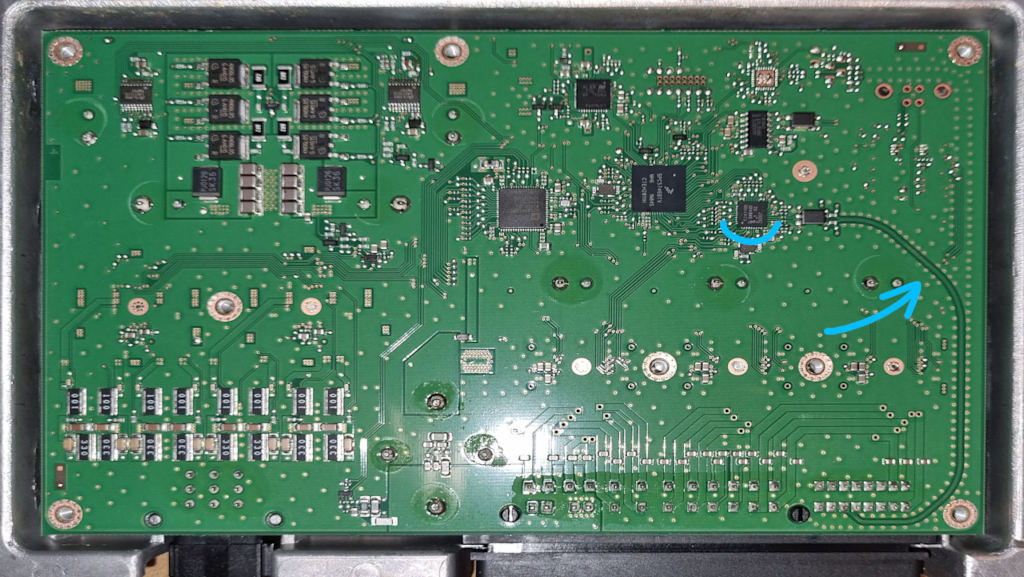
The main thing that draws attention is how the tracks on the right side of the board are laid out with very smooth turns, not the usual 45-degree turns. I think this is where ETH from the name comes into play. These tracks lead into the NXP TJA1100 microchip (through opto- or similar isolation), which provides 100BASE-T1 PHY for Automotive Ethernet.
That looked promising, as it is not some unknown communication medium. The internet mentions the MOST bus being used for some Canton amplifiers, and it’s hard to tell if it would make things more difficult or not.
So my immediate idea is to do a ‘Man-in-the-Middle’ between the car audio head unit and the amplifier to see what is going on there, and if I can make any sense of it.
Connecting to Automotive Ethernet
I hadn’t connected to Automotive Ethernet before (and didn’t even know it existed as a separate thing). So I started to look for an adapter that would allow me to connect Automotive Ethernet with a regular laptop. As I found out, these are usually described as 100BASE-TX to 100BASE-T1 PHY adapters.
One promising option was the NXP RDDRONE-T1ADAPT. It uses the same TJA1100 microchip, which in my mind could minimize any incompatibilities. The RDDRONE adapter has good documentation, and being from a reputable manufacturer gives more hope. But at that time, I would have had to wait for it for 3+ months.
I wanted it sooner.
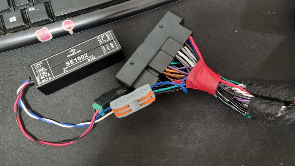
After a few evenings scrolling on AliExpress, I landed on the SPEEDLINK SE1002 from Maxgeek. Some pros:
- it has a good metal case,
- it is compact,
- it is possible to power via USB-C, and
- the customer support is responsive and shared all user manuals they had.
And it wasn’t that expensive in case nothing worked at all.
Connecting to the Amplifier
In the meantime, I needed to solve the connectivity of the above adapter with the circuit between the amplifier and the car audio head unit.
It’s good that I have a friend who has a business installing car audio systems, and apparently, the connector that the amplifier has is pretty common across European car brands.
The solution was to buy one of the OEM adapter harnesses. In my case, the cheapest suitable Audiotec Fischer harness that was in stock. That way, I can connect anything in-between the head unit and the amplifier without touching (as if modifying) the factory wires or connectors.
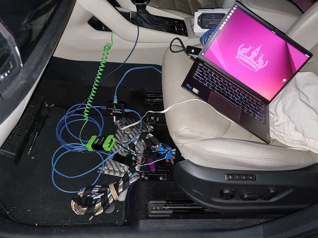
First attempt to use SE1002
Spliced the required wires on the harness to tap into them without breaking the connectivity and connected new wires to the Automotive Ethernet adapter.
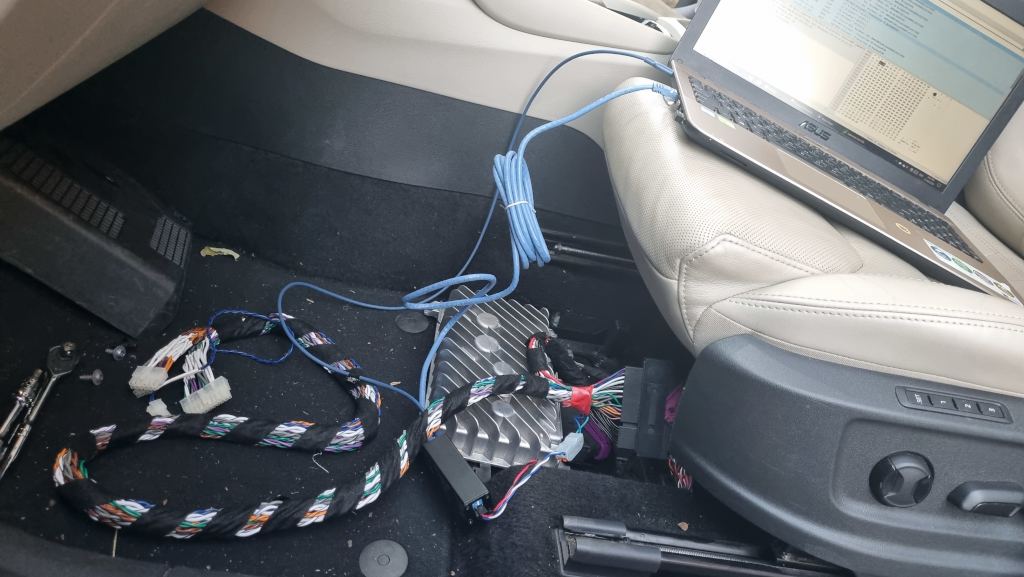
Connected the harness between the amplifier and the head unit without any problems, plugged in the USB-C power, and connected the RJ45 from the laptop to the Automotive Ethernet adapter. The power lights were on, and the Ethernet connection lights (on the RJ45 side) were on, but there was no traffic in Wireshark.
At that point, I didn’t understand what exactly the Master-Slave switch does for the Automotive Ethernet. I wasn’t even sure if the signal levels were compatible with the adapter or if the adapter worked at all.
The best result of the first attempt was that nothing was broken, and no smoke escaped.
Even with the harness, the amplifier was able to talk with the head unit and play music on the speakers through another connector (a 9-pin one for front mid-bass and sub).
Second attempt to sniff the traffic
After contacting the seller of the Automotive Ethernet adapter and getting versions of the user manual they had, there was no indication that I had done something incorrectly.
Tested the wires and connections with the probe to ensure all connectivity was in place and went for a second attempt to check everything in the car.
This time, after a few tries to plug and unplug the harness while keeping the Ethernet adapter always on, I finally saw the green blinking light from inside the adapter (the red one is for power, the green one indicates an available Ethernet link).
Traffic started to flow, but the music from the amplifier stopped playing. I still don’t know the details of why it works that way, but I assume a stable link cannot be established to more than one device on a physical layer.
The traffic was usual Ethernet with IPv6, with devices having properly registered MAC addresses. The main protocols in the sniffed traffic were:
- Precision Time Protocol
- IPv6 neighbour discovery
- An unknown protocol that was identified by Wireshark as Microtik Neigbour Discovery or SKYPE
Clearly, the unknown protocol here is the point of interest. It was UDP coming from the amplifier (as I learned later) to one of the IPv6 multicast addresses, with payloads like:
38 00 2d 01 00 00 00 04  3b 61 00 00
38 00 2d 01 00 00 00 05  3b 63 00 01 03
38 00 2d 01 00 00 00 08  3b 42 03 00 2d 00 04 00
A few hours of searching didn’t help to find a direction.
Microsoft Copilot was helpful in identifying that 38002d01 is some type of header, and at least some of the following bytes represent the length of the payload (like 04 is the length, 3b 61 00 00 is the payload).
But then it read about Automotive application, and gave good vectors to look for:
- Unified Diagnostic Services (UDS) protocol.
- Automotive systems use Audio Video Bridging (AVB) and Time-Sensitive Networking (TSN).
The former one looked like a false positive - I wasn’t able to map the above payloads into the protocol frames and messages. Also, Wireshark claims that it can identify the UDS protocol, but it didn’t see it as such.
The latter was a good hint overall, leading me into a rabbit hole of reading standards documentation. The first promising hint was that on the amplifier’s circuit board, the TJA1100 chip was connected to the NXP MPC5746C microcontroller. According to the specification, it supports AVB through Ethernet. Another promising hint was that AVB requires three extensions to comply with IEEE802.1:
- IEEE802.1AS – timing and synchronisation for time-sensitive applications (gPTP)
- IEEE802.1Qat – stream reservation protocol (SRP)
- IEEE802.1Qav – forwarding and queuing for time-sensitive streams (FQTSS).
And I saw the PTP traffic in the capture mentioned above, which is likely a prerequisite for AVB.
Third attempt to capture the traffic
At this point, I already realized what the Master-Slave switch does - it indicates which device initiates the physical link establishment.
Because in my second attempt I wasn’t able to be a proper ‘Man-in-the-Middle’, I decided I needed to control who has a physical connection to the Ethernet adapter. The simplest solution was to break the circuit by cutting one of the wires and soldering in a switch I found somewhere on the shelves.
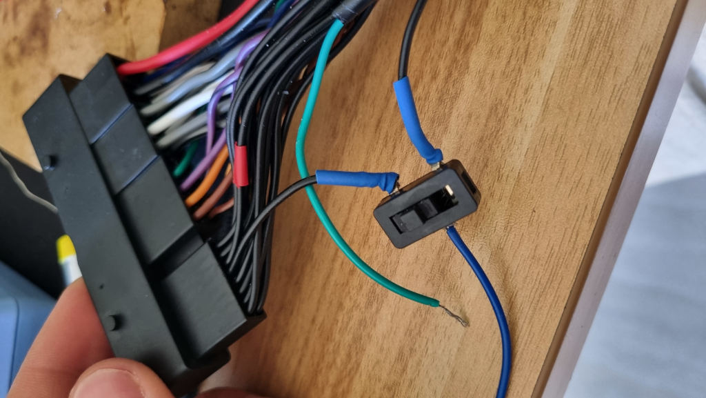
To connect to the amplifier, I enable Master mode for the adapter and flip the switch in one direction. To connect to the head unit, I set adapter to Slave mode and flip the switch back. The switch isn’t of great quality and doesn’t necessarily have contact bounce, but it needs a bit of extra help to establish a connection.
This time, I was able to ensure that the head unit multicasts UDP to:
ff14::5always with the message containing the same payload:20 73 0c 00 00 00 00 08 73 00 04 00 01 00 00 00(every 200ms)ff14::1:2dwith two payloads:30 00 2d 01 00 00 00 04 40 00 01 0aand30 00 2d 01 00 00 00 02 1b 42.
The amplifier only multicasts to ff14::1:2d. I wonder if the head unit performs discovery this way - different types of amplifiers may respond to different addresses?
The payloads were similar to those from the second attempt, with an addition - I was able to see some ASCII abbreviations, like SKCANCEQ (which I assume stands for Skoda Canton Custom Equalizer, but it’s not important at this stage).
I’ve tried to send replicas of some of the packets I’ve seen with Scapy - found it through Wireshark Wiki. And it is the most suitable tool for me at this stage. The way it stacks the layers of different protocols is very visual to what is going to build the packet: Ether() / IPv6(dst='ff14::1:2d') / UDP(sport=42993,dport=42514) / "\x38\x00\x2d\x01\x00\x00\x00\x04\x3b\x61\x00\x00".
Also, I don’t know exactly what I did - turning the car power on and off, touching the not-so-great-quality switch on the harness, or switching Master-Slave on the adapter - but the head unit started sending Real-time Transport Protocol (RTP) and AVB RTP Control Protocol (RTCP) packets.
Both RTP and AVB RTCP were multicasted to ff14::2:2. The RTP payload of Type 98 (which I learned is dynamic) was always empty.
So, it definitely requires some negotiation and understanding between the sender and receiver before the head unit will start to send anything meaningful.
Time-sensitive networking
For now I don’t know how important to have a TSN negotiation happening between the amplifier and the head unit, but that looked as a simple step to tackle. I find it non-trivial to find actual differences between software and hardware timestamping (like what guarantees one can provide that other cannot). And equally challenging to find whether certain Ethernet adapter has hardware support or not, and my USB-C one that I use with the laptop definitely doesn’t.
Three most common software implementations:
- Avnu/gptp - has a bug that it cannot use adapter with name 15 characters or more (according to the code I believe intention was to support 16 characters, but off-by-one error :). Created alias for the network interface, app started, but there is no software timestamping.
- ptpd - only supports IPv4, while Skoda’s network is IPv6.
- linuxPTP/ptp4l - worked well
Need to use Automotive profile configuration. But essentially this didn’t help and ‘ptp4l’ on a laptop kept getting into failed state after a few peer request attempts. There is a definitely a difference that software timestaping missing ‘PTP_TIMESCALE’ flag in its packets, and wasn’t able to find if this is something that is only available through hardware support.
Sniffing
Since last time I wasn’t sure if the direction I was going was the right one, I wrote an email to the manufacturer of the head unit, and to folks from mObridge / Fiberdyne (they have a few praises on the diymobileaudio.com forum). As expected, there was no response from the manufacturer, but the response from Fiberdyne exceeded all my expectations - Julian explained that my approach was somewhat correct, but that replacing either the amplifier or head unit in an attempt to understand how they communicate is a very difficult approach. He recommended that I get a second Automotive Ethernet adapter and a proper network tap (his recommendations were the Intrepid RAD-Moon and SharkTap 10/100).
Ordered the adapter straight away, but I was pretty stubborn (and cheap) - tried to avoid buying a network tap by:
- looking for a network hub (their selling price now is like they are made of gold),
- trying a passive tap (crossing physical wires), or
- using Cisco’s Switch Port Analyzer.
All of these had various levels of success, but generally no optimal result. So, I eventually bought a network tap later.
With everything together I was able to see the communication between the devices. Generally applied to all the communication - uses VLAN with ID 3 and IPv6.
gPTP does its magic with sync, follow up and peer delay packets. Clock source is 22:22:22:22:22:22, and doesn’t come from the head unit. Amplifier responds well.
Then the head unit sends a SOME/IP packet every 200 ms to the multicast address ff14::5, but I think this isn’t used in the case of Canton.
Configuration between headunit and amplifier is exchanged through UDP multicast to ff14::1:2d - both of them send custom UDP payload there.
Wireshark cannot identify the protocol they use. I tried to reverse engineer the fields as much as I could, with the help of LLMs:
Notes for the below table:
- Header: The first byte is always
30for the head unit, and38for the amplifier - Envelope is not always present - so no length and no flags.
- Command Type: Always
1bor2bfrom the head unit (looks like1bis a read request,2bis a request to store a new value). From the amplifier always returns as3band4b
| Header | Envelope length | Flags for command envelope? | Command length | Command Type | Parameter | Payload |
|---|---|---|---|---|---|---|
| Head unit: | ||||||
30002d01 |
0000001a |
afff |
00000012 |
2b |
5e |
08534b43414e43455108534b43414e414c4c # This is SKCANCEQ SKCANALL |
| Amplifier: | ||||||
38002d01 |
0000001a |
8fff |
00000012 |
3b |
5e |
08534b43414e43455108534b43414e414c4c |
38002d01 |
0000001a |
8fff |
00000012 |
4b |
5e |
08534b43414e43455108534b43414e414c4c |
The audio itself uses the RTP / RTCP protocol and streams sound as is, without any encryption (luckily).
Head unit multicasts RTP and RTCP to two destinations:
- Screen taps (with navigation going here as well). This RTP payload is 3 times longer than the ones for music, looks like it is 6 channels of 16 bit 48kHz:
- IPv6: ff14::2:1
- VLAN priority 6
- Name
ANN\n(announcements?) - Type DynamicRTP-102
- The music itself in 48kHz 16bit format as raw as possible (I was changing big-endian to little-endian and adding headers, and played it as WAV):
- IPv6: ff14::2:2
- VLAN priority 3
- Name
ENT\n(entertainment?) - Type DynamicRTP-98
Amplifier sends all the post-processed music (with applied equaliser etc) back to the:
- IPv6: ff14::2:5
- VLAN priority 6
- Name
TEST - Type DynamicRTP-98
One thing that I never though of, but now it makes total sense - parking sensor has its own beeper and doesn’t rely on the headunit at all (and that way it can start beeping as soon as car is started, before the headunit loaded)